Introduction #
This application example demonstrates the implementation of a three-phase grid-tie inverter with boost converter on PE-RCP Box using MATLAB Simulink as a development environment.
Required Tools #
Make sure to prepare the MATLAB environment by following the procedure provided in the Getting Started Guide. The following tools are required for understanding and implementing the example given in this application example:
- MATLAB R2019b or newer
- MATLAB Embedded Support package for C2000 processors
Hardware Overview #
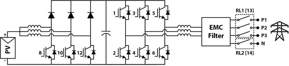
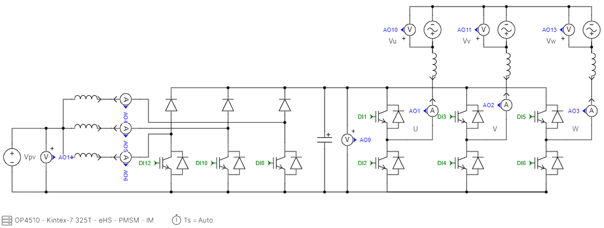
This example uses a 2-level inverter, a boost converter (3 converters in parallel), and an EMC filter with disconnection relays. A simplified schematic of the converter circuit is shown below:
Control Implementation #
Requirements #
The following equipment/facilities are required for practical verification of this example:
- PE-RCP Box
- OP4510 HIL Real-Time Simulator
- PELab-6PH
- Programmable DC Power Supply
- Three-Phase Grid Supply
Operating Conditions #
The following table provides relevant implementation specifications:
| PARAMETER | VALUE |
| PWM Switching Frequency | 40 kHz |
| Dead-Time | 200 nSec |
| DC-Link Voltage Set Point | 720 VDC |
| Grid Voltage | 380 VAC L-L |
| Grid Frequency | 50 Hz |
| DC Input Voltage | 180 V – 200 V |
Control Algorithm #
Inverter Control #
The three-phase grid-tie inverter is controlled using a vector current control. The following figure depicts the basic control diagram of the implemented algorithm:
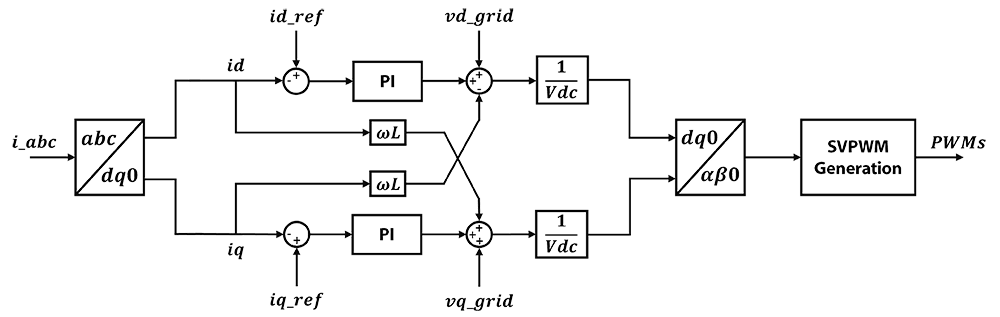
The measured grid phase voltages and currents are converted to the rotating reference (DQ) frame. Phase-Locked Loop (PLL) is used to estimate the grid phase angle which is used in the conversion. A PI controller is then used to compensate for the error in phase currents. After that, an inductive decoupling compensation and normalization are added to the calculated duty cycles. An SVPWM technique is then used to generate the gating signals for the inverter switches.
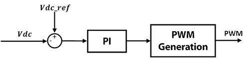
Boost Converter Control #
A simple PI controller is implemented for the boost converter control to achieve the desired DC-link voltage. Kindly note that this control is very simple and will require additional hardware-based current protections to avoid inductor saturation and leg current overload (available in the PELab-6PH system). It is also essential to apply a maximum duty cycle limit for the boost converter PWM depending on the input voltage to avoid short-circuiting due to inductor saturation. If a higher input voltage than the set point is supplied to the inverter, the boost converter will not be required for inverter operation. In summary, the DC-Link voltage must be at least 50V higher than the peak grid voltage to ensure proper current flow from the inverter to the grid.
Workflow #
The PE-RCP Box can be programmed directly from MATLAB Simulink which allows us to rapidly prototype our control system. The basic workflow diagram of the implemented system is shown below:
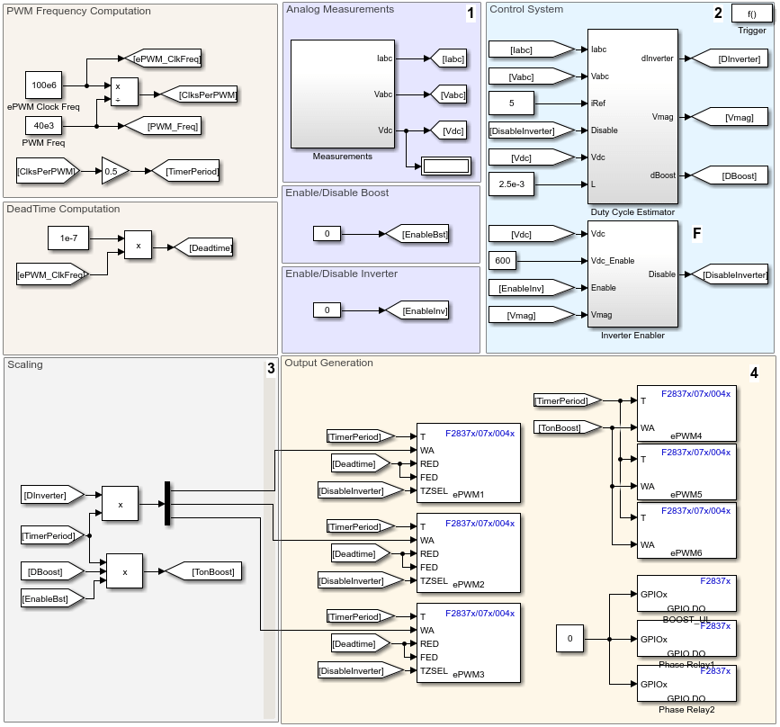
The following section provides a brief overview of the essential blocks used in the MATLAB Simulink model:
1. Analog Measurements #
C2000 ADC blocks are used for the measurement of grid phase voltages, leg currents, and the DC-Link voltage.
2. Control System #
The Control System has a Duty-Cycle Estimator block used for computing the required duty cycle values for the inverter as well as the boost converter. And an Enable/Disable block for protection. Below is an overview of the internal blocks:
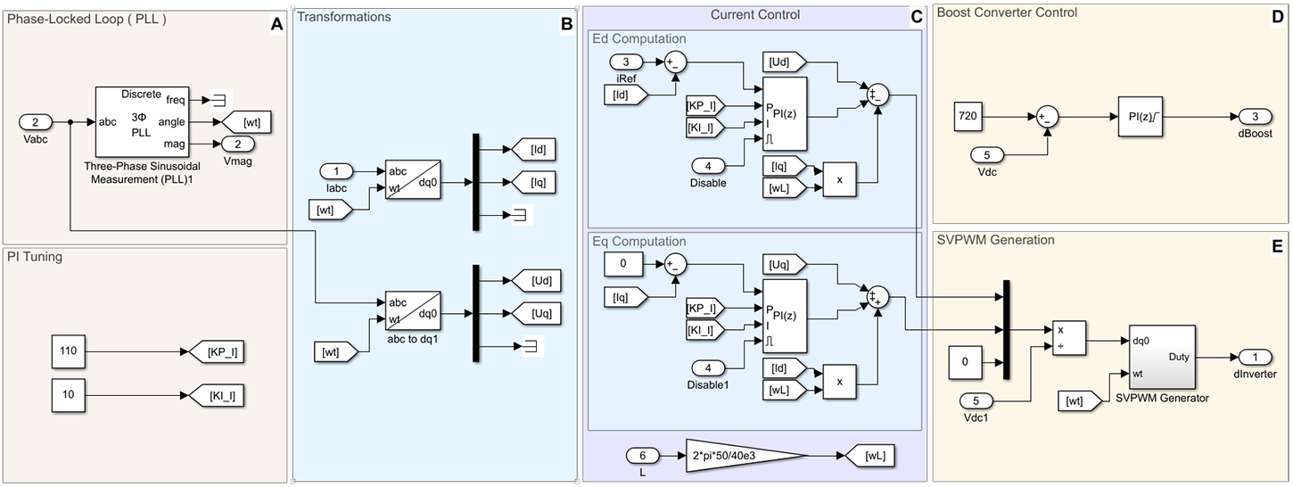
A. Phase-Locked Loop (PLL) #
The PLL block is used to synchronize the control to the grid phase angle. The acquired phase angle is used for the Park/Clarke transformations as well as the synchronization of the grid phase voltages and injected phase currents.
B. Transformations #
Implements transformations to convert between stationary frames (ABC and αβ) and rotating frames (DQ).
C. Current Control #
A PI-based current control is implemented on DQ-currents obtained after transformation. Inductive decoupling compensation is implemented for robust current control.
D. Boost Converter Control #
Implements a PI controller to generate the duty cycle for the boost converter
E. SVPWM Generation #
Implements Space Vector Pulse Width Modulation (SVPWM) which provides higher voltage, high reduction in the dominant harmonics, and lower total harmonic distortion for a three-phase inverter.
F. Enable/Disable Control #
The enable/disable control is implemented on the following:
Boost Converter: A manual on/off control to enable or disable the boost converter if not used by the system.
Relays: The relays are only turned on after ensuring the DC-Link is charged to avoid inrush current from the grid which can damage the power modules. Note that this is absolutely essential since when the DC-Link is not charged, the inverter switches body diodes act as an uncontrolled rectifier, and therefore unpreventable short circuit current may flow to the inverter and damage the switches permanently.
Three-Phase Inverter: It is enabled only if the following conditions are fulfilled:
- The DC-Link is precharged and has a higher voltage than the grid voltage.
- The measured grid voltage magnitude lies in the specified range.
- The inverter is enabled by the user.
3. Scaling #
The duty cycles of the three-phase inverter, as well as the boost converter, are multiplied by the timer period of our system to generate a counter signal for the ePWM blocks.
4. Output Generation #
C2000 ePWM blocks are used to generate the PWM signals for the boost converter and the three-phase inverter. The trip-Zone sub-module is used for safe switching.
Implementation & Results #
This application example is tested with HIL real-time simulator (OP4510 from OPAL-RT Technologies) as well as actual power electronics hardware using the PELab-6PH power electronics rapid development system.
HIL Real-Time Simulation (OP4510) #
The power supply, power electronics, and the grid are simulated using the OP4510 HIL real-time simulator provided by OPAL-RT Technologies.
The HIL simulation is run by RT-LAB using the eHS FPGA-based solver. The following power circuit is implemented using the OPAL-RT Schematic Editor:
Results #
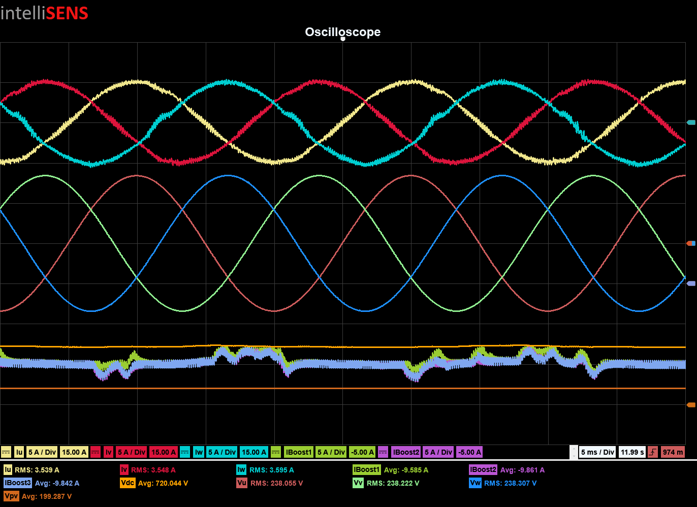
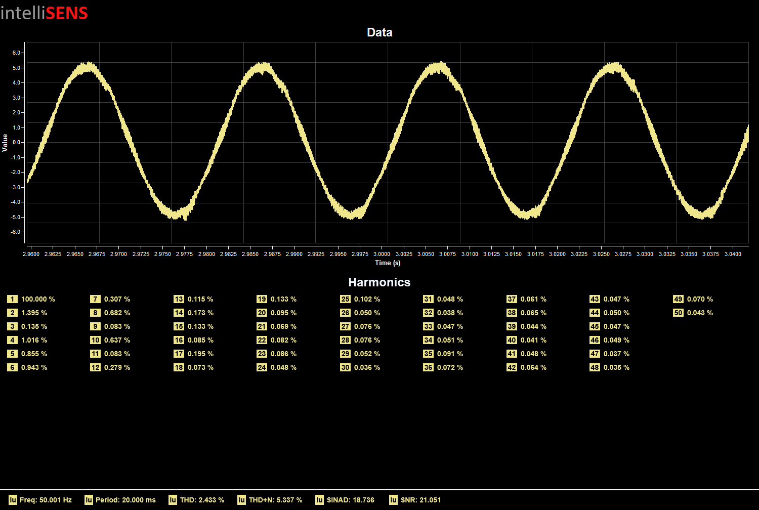
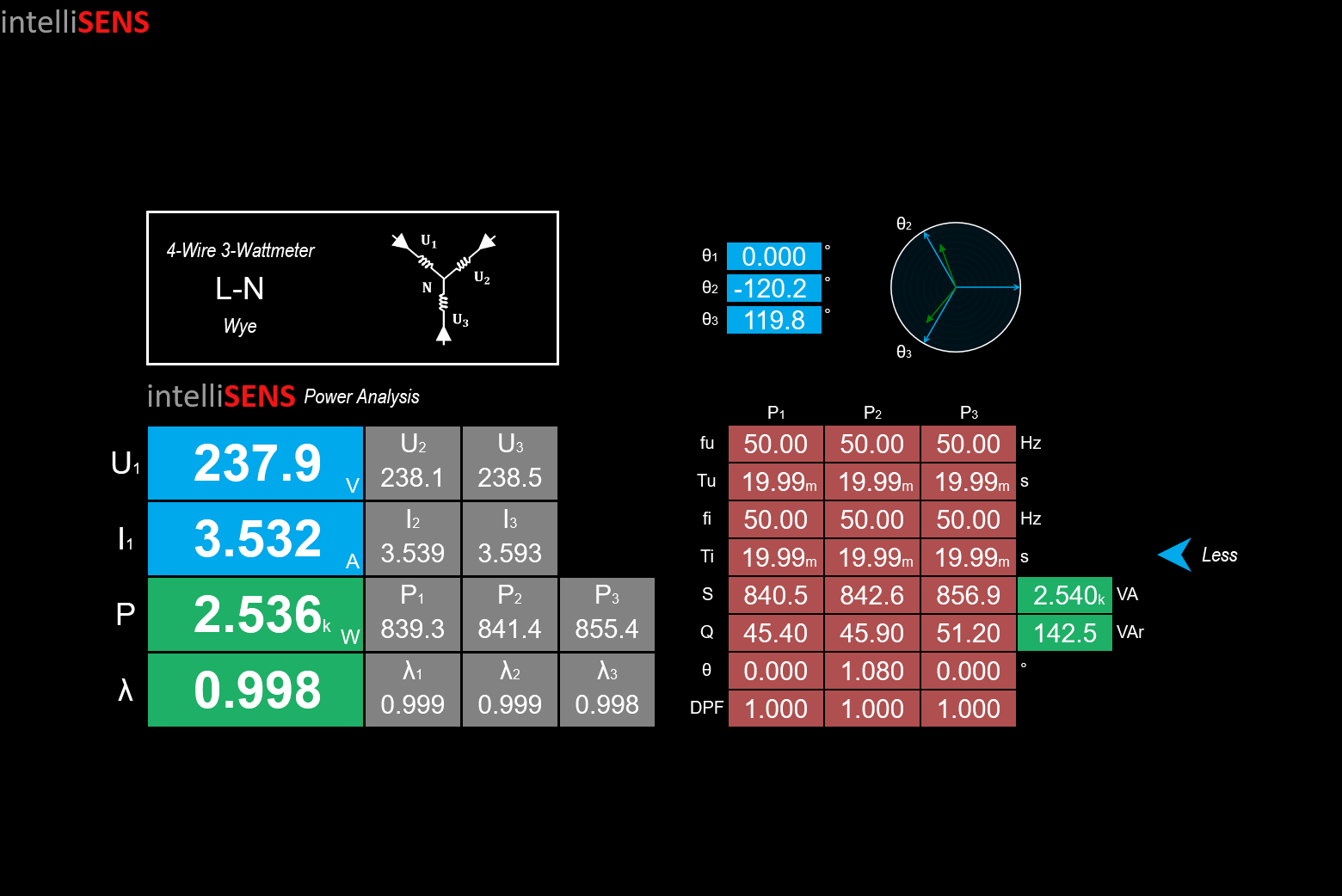
The implementation results are acquired using the PEController which is part of the PELab-6PH system. The PEController provides integration to the intelliSENS real-time monitoring and recording software. Below are the results for the 5 A peak (~3.5 A RMS) reference point. The PELab is operating in RCP to HIL Mode.
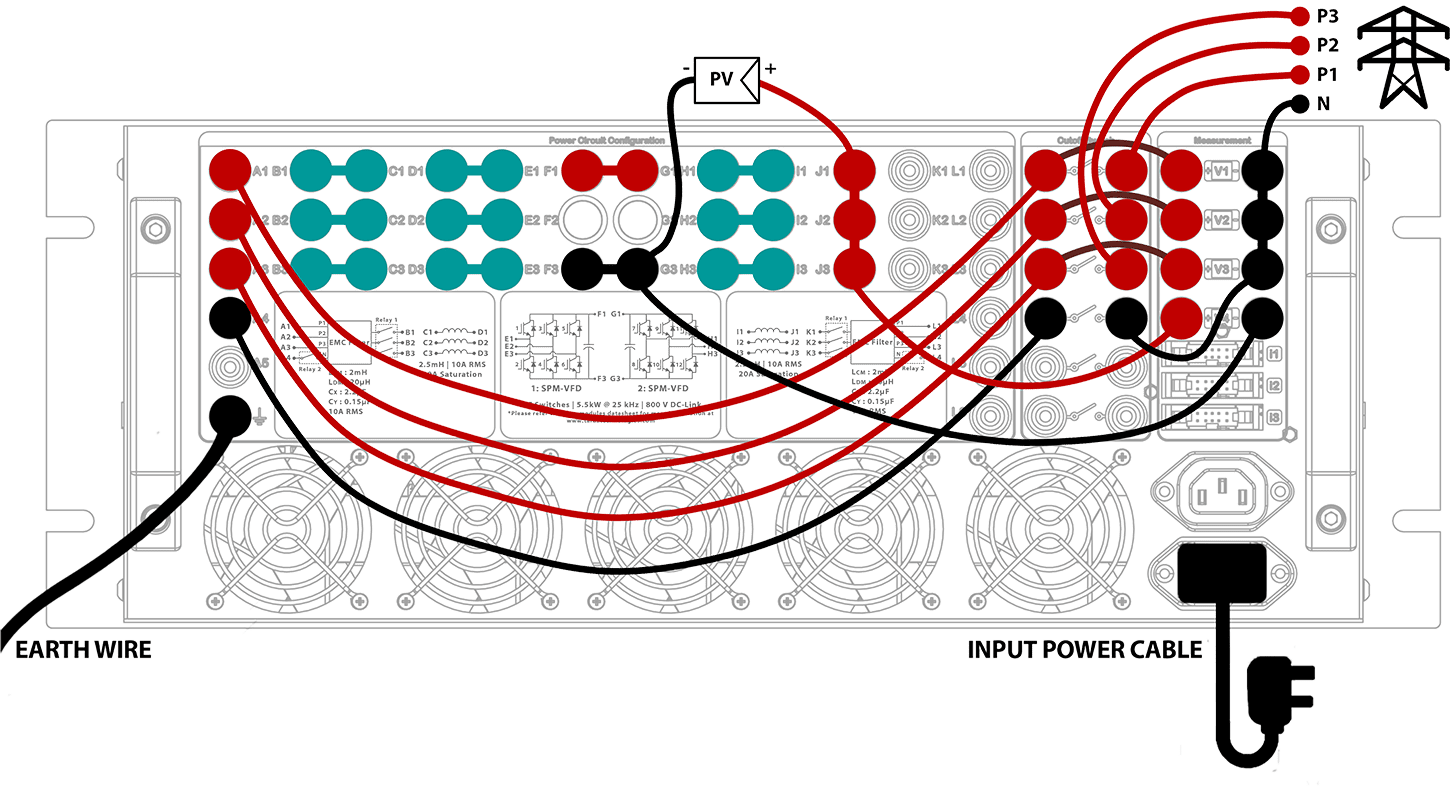
Power Electronics Hardware Implementation (PELab-6PH) #
The hardware implementation of the power stage is done using the PELab system. The PELab-6PH configuration provides two three-phase inverters. The first inverter is used as a 2-level 3-phase inverter while the second inverter is used as a parallel boost converter. Inductors, EMC filters, and relays are also available in PELab-6PH. The following figure shows the connections diagram of the PELab-6PH:
WARNING! THE FOLLOWING PROCEDURES MUST BE FOLLOWED WHILE TURNING THE SYSTEM ON AND OFF. FAILURE TO DO SO MAY RESULT IN PERMANENT DAMAGE TO THE EQUIPMENT.
Turn-on procedure #
- Make sure that all protections on the PELab system are enabled and the DC-Link is discharged.
- Upload the Simulink model on the PE-RCP box using the monitor and tune button.
- Make sure that boost converter and inverter controls are disabled in the model.
- Turn on the input DC power supply.
- Enable the boost converter from the model. Make sure that the DC-Link is being regulated at the desired voltage.
- Turn on the cutoff switch to connect to the grid and wait for about 2 seconds for the PLL to synchronize.
- Enable the inverter from the Simulink model.
- Once the inverter is enabled, the performance of the grid-tie inverter can be monitored by changing the reference current for injection.
Turn off procedure #
- Disable the inverter from the Simulink model.
- Turn off the cutoff switch to disconnect the grid.
- Turn off the input DC power supply and wait for the DC-Link to discharge.
- Stop the monitor and tune the session.
Results #
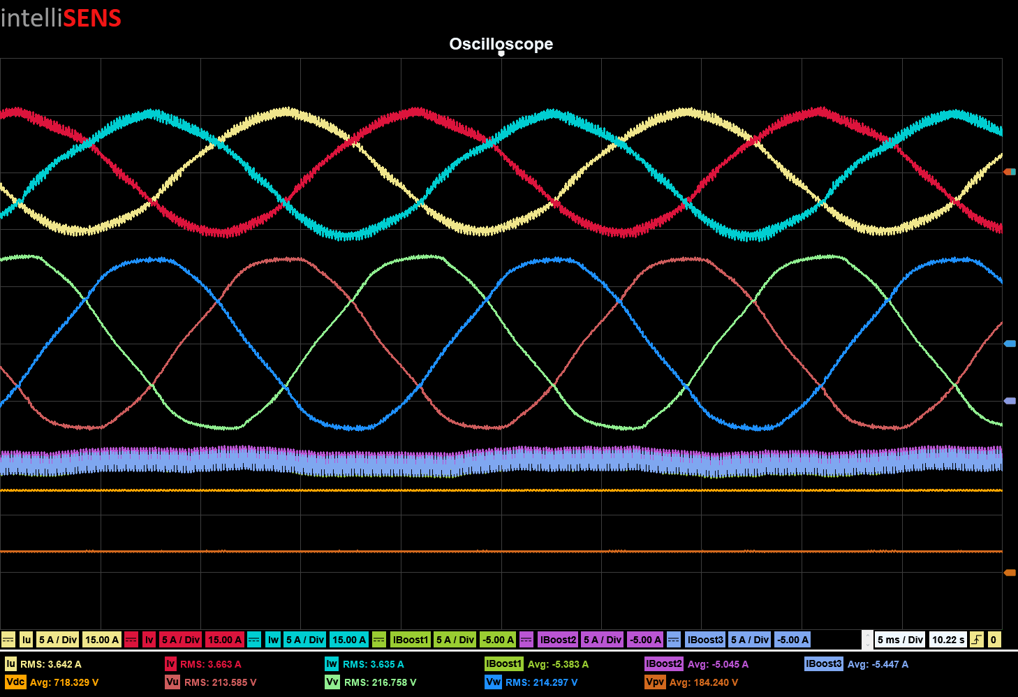
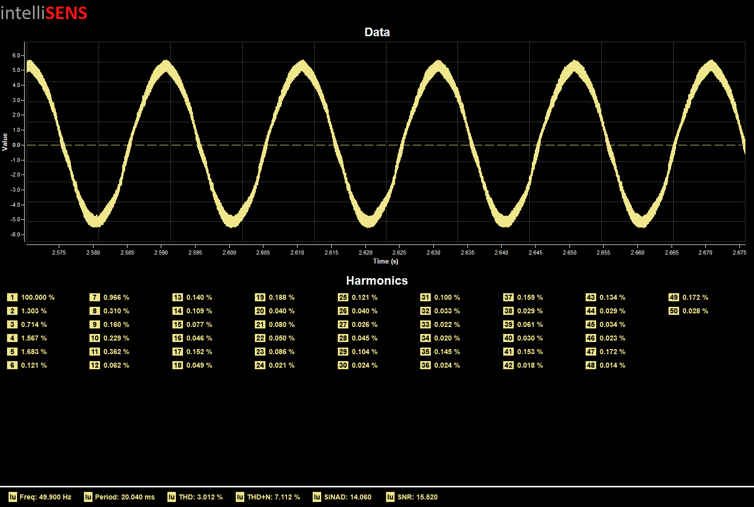
The implementation results are acquired using the PEController which is part of the PELab-6PH system. The PEController provides integration to the intelliSENS real-time monitoring and recording software. Below are the results for the 5 A peak (~3.5 A RMS) reference point. The PELab is operating in RCP to Power Mode.

Results Summary #
| Parameter | HIL Implementation | Power Implementation | Unit |
| Iu | 3.539 | 3.642 | A (RMS) |
| Iv | 3.548 | 3.663 | A (RMS) |
| Iw | 3.595 | 3.635 | A (RMS) |
| Iboost1 | 9.585 | 5.383 | A (AVG) |
| Iboost2 | 9.861 | 5.045 | A (AVG) |
| Iboost3 | 9.842 | 5.447 | A (AVG) |
| Vu | 238.055 | 213.585 | V (RMS) |
| Vv | 238.222 | 216.758 | V (RMS) |
| Vw | 238.307 | 214.297 | V (RMS) |
| Iu Current THD | 2.433 | 3.012 | % |
| Iu Current THD+N | 5.337 | 7.112 | % |
| Output Power | 2.536 | 2.36 | kW |
| Power Factor | 0.998 | 0.996 | – |