Introduction #
This article describes how to get started with embedded development on PEController.
Pre-requisites #
The following tools are prerequisites for understanding and implementing the example given in this article:
- STM32CubeIDE 1.9 or newer
- STM32Cube_FW_H7_V1.7.0 or newer
- STM32CubeMX 6.0.0 or newer
- PEController Board Support Package
Hardware Overview #
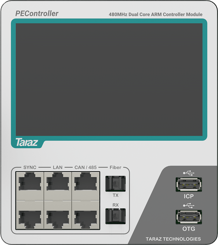
Prepare the PEController for running the demo application, using the following steps.
- Power up the PEController. (In the case of standalone PEController use the 15V adapter to power up the PEController).
- Connect the ICP USB to the Computer via a Type-A USB cable.
PEController Board Support Package #
The PEController is supported by open-source embedded C libraries on GitHub. The open-source package is named PEController Board Support Package (BSP). These libraries also include sample application examples that can accelerate the development. These libraries are a prerequisite for this article.
Downloading the PEController BSP #
Download the current release of PEController BSP using the following steps:
Step 1: Go to the link https://github.com/Taraz-Technologies/PEControllerBSP.
Step 2: Press the “Code” button as shown in the image below and click “Download ZIP” to get the most recent version of PEController BSP.

Step 3: Extract the folder from the downloaded zip file.
Step 4: Click here to access the documentation for PEControllerBSP
PEController BSP Brief #
Directory Overview #
The following section describes the current directory structure of the PEController BSP:
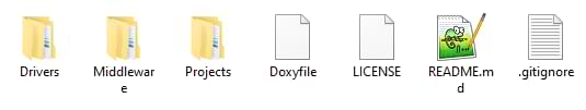
Drivers #
This folder contains the device drivers for PEController.
- BSP: Contains the BSP drivers provided by Taraz Technologies.
- PEController
- ADC: Contains the ADC-related device drivers.
- Common: Contains the general sharing and definitions related to device drivers.
- Components: Contains the different component drivers.
- DigitalPins: Contains the Digital IO-related device drivers.
- Display: Contains the display-related device drivers.
- intelliSENS: Contains the device drivers for intelliSENS software integration.
- PWM: Contains the PWM-related device drivers.
- PEController
- CMSIS: Contains the Common Microcontroller Software Interface Standard (CMSIS) standard device drivers.
- STM32H7xx_HAL_Driver: This contains the device provided by STMicroelectronics.
Middlewares #
This folder contains the support libraries for the drivers.
- ST: Contains the support libraries for USB and Networking etc. provided by STMicroelectronics.
- Taraz: Contains the support libraries for Control System Design (such as Clarke/Park Conversions, Digital Filtering, PLL generation, etc.) provided by Taraz Technologies.
- Third_party: Contains third-party support libraries such as LWIP, FreeRTOS, and FatFS.
Projects #
This folder contains the application examples provided in the BSP.
- PEController
- Applications.
- PEController_Template: Template project for creating new quick projects.
- PELab_OpenLoopVFD: Basic Implementation of Open Loop V/f Control Implemented for different variants of PELab as well as independent PEController boards.
- Applications.
Running the Open Loop V/f Example #
This article uses the PELab_OpenLoopVFD example project to demonstrate the usage with PEController. Make sure to install all the prerequisite tools before proceeding further.
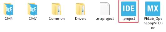
Step 1: Open the directory containing the PEController BSP downloaded from GitHub.
Step 2: Open the “.project” file in {Project_path}/ Projects/PEController/Applications/PELab_OpenLoopVFD. This will add the project with its two nested projects in the STM32CubeIDE workspace.
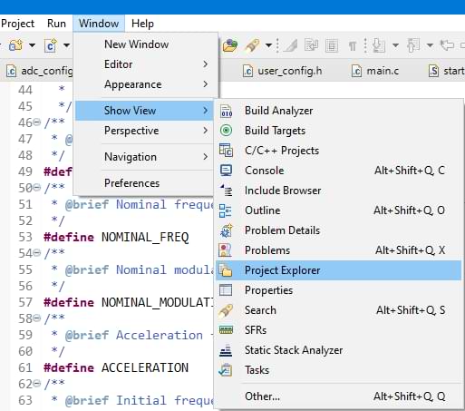
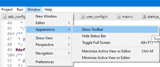
Step 3: Open the Project Explorer from Window in Menu Item as shown in the image below:
Step 4: Make sure to enable the Toolbar from Window in Menu Item as shown below:
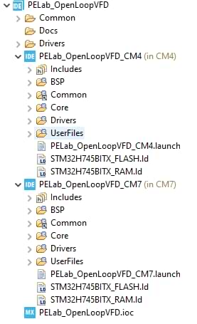
Step 5: Expand the PELab_OpenLoopVFD project. It is visible in the project, that the project has two nested projects, one for the CM4 core while the other is for the CM7 core as seen in the below image:
Step 6: The logic in BSP is divided such that measurement acquisition, LCD display, and other auxiliary functionalities are controlled by the CM4 core while the CM7 core is used for the implementation of the control algorithm for better control performance.
Step 7: Both projects contain the following structure:
- BSP: Contains the BSP drivers.
- Common: Contains the shared files such as configurations that are shared by both CM4 and CM7 cores.
- Core: Contains the main and other files generated by the STM32CubeMX software.
- Drivers: Contains the STMicroelectronics drivers.
- UserFiles: Contains the project-related files.
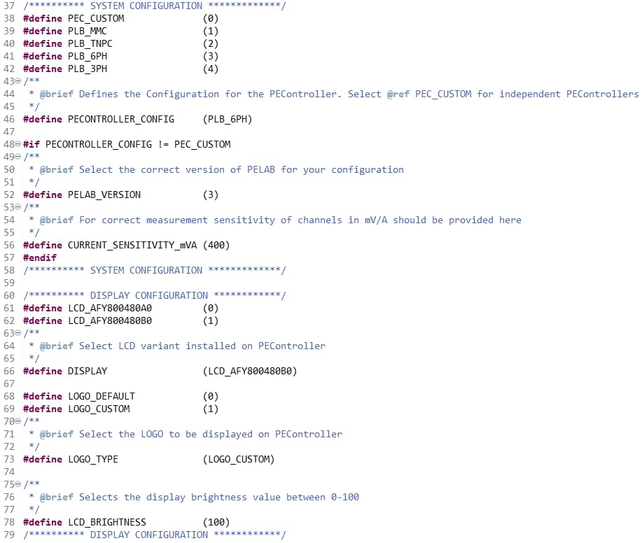
Step 8: Edit the following information in the “user_config.h” file in Common/Inc:
- Select the hardware type from the parameter PECONTROLLER_CONFIG. Select PEC_CUSTOM for independent PEController, while for PELab select the appropriate PELab configuration.
- In case the PEController is mounted in the PELab, select the appropriate value of PELAB_VERSION and CURRENT_SENSITIVITY_mVA. The relevant information is available in the PELab datasheet.
- Select the appropriate display module for your PEController.
Step 9: Right Click PELab_OpenLoopVFD_CM4 and click build project:
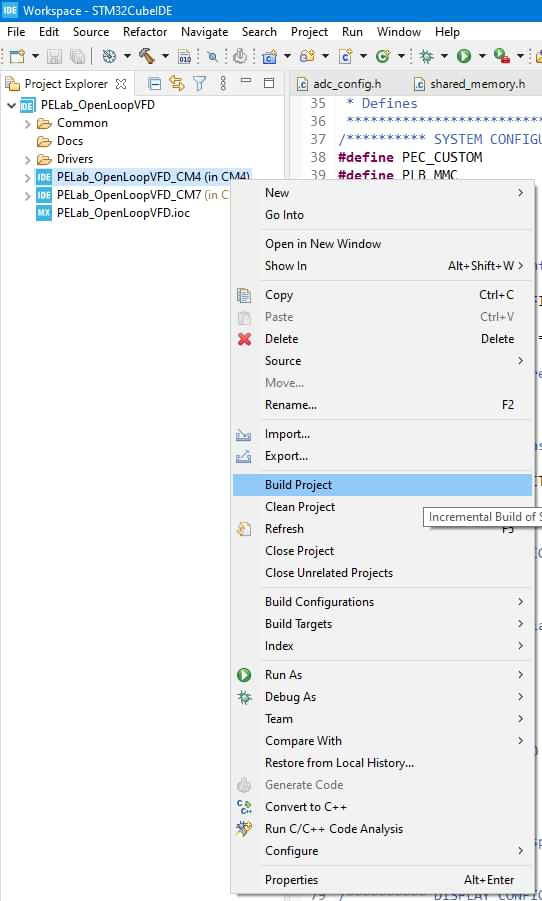
Step 10: Right Click PELab_OpenLoopVFD_CM7 and click build project.
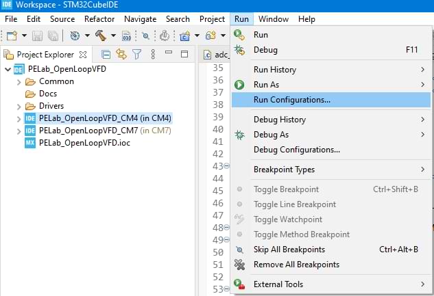
Step 11: Click Run and then Run Configurations… in Menu Items:
Step 12: Go to the Startup tab in PELab_OpenLoopVFD_CM4:

Step 13: The figure above shows that the PELab_OpenLoopVFD_CM4 project is configured not to build or download the code to the CM4 core. This option enables the provision to debug both CM4 and CM7 core at the same time. The CM7 project as shown in the figure below is responsible for programming both the CM7 and CM4 core:
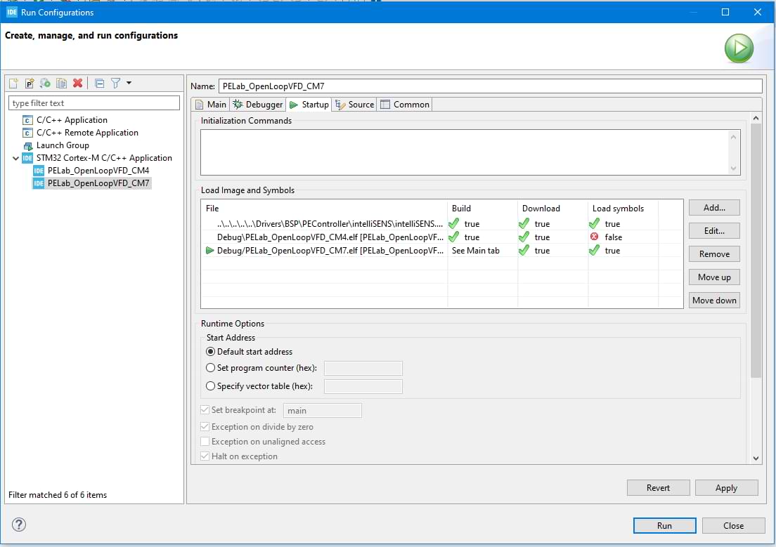
Step 14: Make sure that the CM7 project is selected in the above window and press Run to upload the code to both cores.
Implementation and Results #
This section provides the practical implementation of Open Loop V/f Control on an inductive load.
Required Equipment #
The following equipment is required for practically verifying the functionality of the V/f Controller.
- PELab with integrated PEController
- Three-phase Load (Induction Motor or Inductors)
- DC Power Supply
Implementation Details #
The implementation is possible for a variety of configurations of PELab. Standalone PEController requires an external power stage and the three-phase load for the implementation of this example. This guide discusses the results of the Open Loop V/f example on PELab (PLB-6PH) with internal inductors as a three-phase load.
The example demonstrates the control of the modulation index based on current frequency as the DC Link voltage is constant. At the start of the demonstration, the output frequency is 1Hz. The frequency increases with a designated acceleration factor until it reaches the required frequency value. This demonstrates the soft-start capability for three-phase motors so that high current requirements at startup can be avoided.
The following table provides relevant implementation specifications:
| PARAMETER | VALUE |
| PWM Frequency | 40 KHz |
| Output Required Frequency | 25 Hz |
| Output Initial Frequency | 1 Hz |
| DC Link Voltage | 50 V |
| Inductance | 2.5 mH |
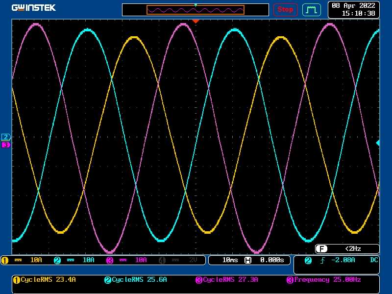
Results #
This section provides the output current waveforms for the three phases at the required frequency. Each current waveform is represented using a different color. Relevant measurements are also available in the image.
Debugging the Example #
This section describes the procedure for debugging both CM7 and CM4 core for the project simultaneously. Use the following steps to debug the open-loop v/f project.
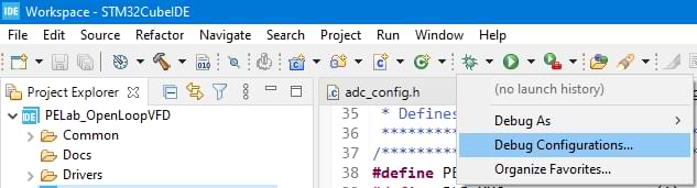
Step 1: Click the arrow next to Debug icon in Toolbar and click the Debug Configurations menu item as shown in the image below:
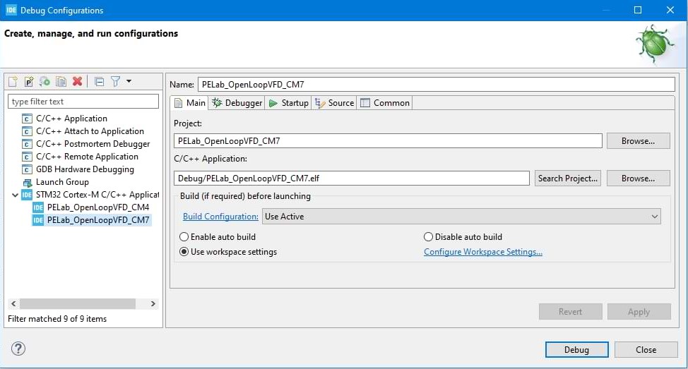
Step 2: Select PELab_OpenLoopVFD_CM7 launch configuration and press Debug button:
Step 3: Press the resume button in Toolbar once the application is loaded. Make sure that the application is completely loaded before pressing the resume button to avoid any errors.
Step 4: Click the arrow next to Debug icon in the Toolbar and click the Debug Configurations menu item:
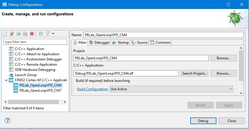
Step 5: Select PELab_OpenLoopVFD_CM4 launch configuration and press Debug button.
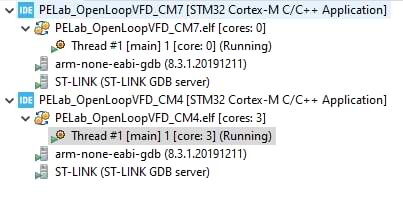
Step 6: The Debug window should look like the image below, where both projects will be running:
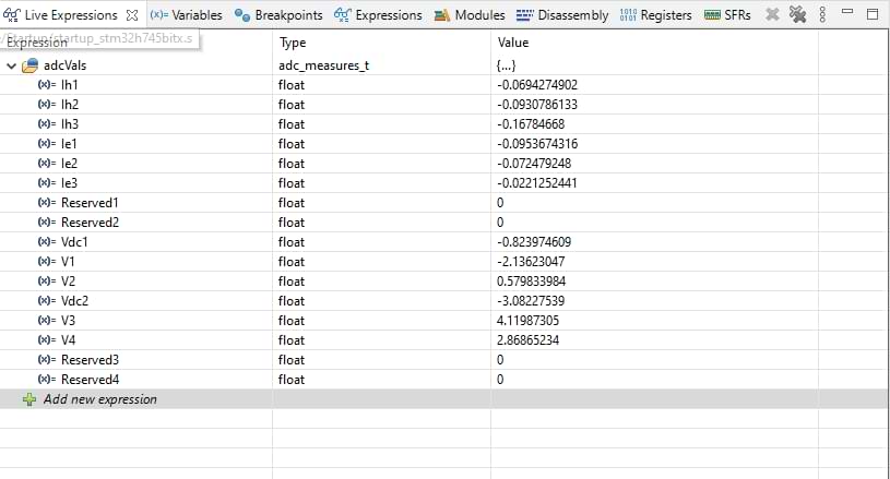
Step 7: Open the Live Expressions tab, write adcVals in the expression column, and press enter. Press the arrow on the side of adcVals to see the live value feedback from the analog channels. The structure for adcVals is defined in adc_config.h and its members may vary depending upon your configuration. The live feedback view will be similar to the image below and the values will be constantly changing:
Step 8: Press the terminate button in Toolbar for both projects to terminate the debugging session.