Introduction #
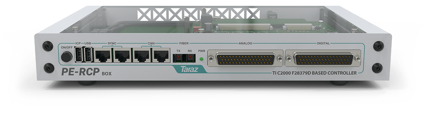
PE-RCP Box is a Rapid Control Prototyping Solution based on TI C2000 F28379D Microcontroller, specifically designed to support block-based programming in MATLAB/Simulink and PSIM, which makes it an essential for developing control algorithms for power electronic systems. This guide describes how to get started with MATLAB/Simulink programming on PE-RCP Box.
*Note: This document is also applicable for PE-RCP
Pre-requisites #
The following tools are prerequisites for understanding and implementing the example given in this article:
- PE-RCP Box
- MATLAB R2019b or newer
- Code Composer Studio Version 11
Hardware Overview #
PE-RCP Box can be used to implement control algorithms on power electronics hardwares as well as Hardware in Loop (HIL) systems. It also allows diagnostics and fault reporting through different links/ports available like Fiber, CAN, USB and DB-50/ DB-37 Female Connectors.
Follow these steps to prepare PE-RCP Box for running the demo application:
- Power up the PE-RCP Box using 15V adapter.
- Connect the ICP USB to the computer via a Type-A USB cable.
- Press the ON/OFF button on the front panel.
C2000 Support Package for MATLAB #
Install Embedded Coder Support Package for Texas Instruments C2000 Processors for MATLAB. Make sure to connect to the internet before proceeding further.
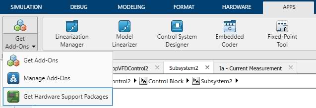
Step 1: Click on Get Hardware Support Package in “Apps” Tab:
Step 2: Select “Embedded Coder Support Package for Texas Instruments C2000 Processors” and press Install:

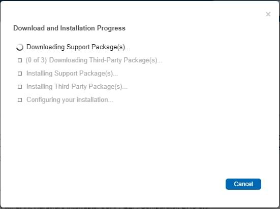
Step 3: After installation starts, the following window displays the installation status:
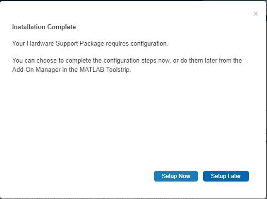
Step 4: After installation is completed click “Setup Now”:
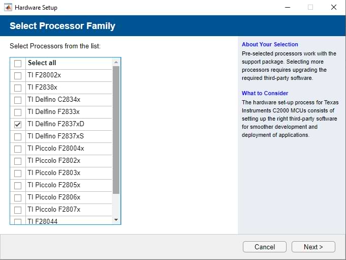
Step 5: Select TI Delfino F2837xD in Processor family and click “Next”:
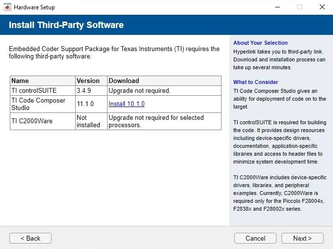
Step 6: Install required Third-Party Software and click “Next”:
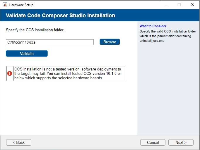
Step 7: For CCS Installation Folder, click on “Validate” (Ignore the waring) and then click “Next”:
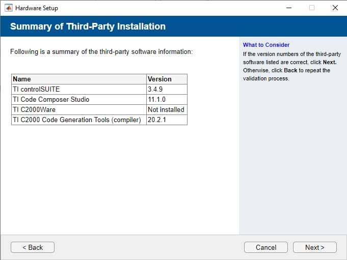
Step 8: Review installation summary and click “Next” to finish the setup:
Running V/f Control Example #
This document uses “PE-RCP V/f Control Example“ to demonstrate the usage with PE-RCP Box. Make sure to install all the prerequisite tools before proceeding further.
Step 1: Download and open the attached example.
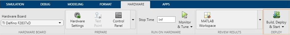
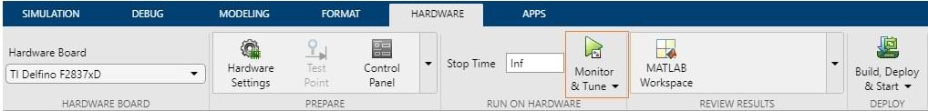
Step 2: Make sure that the hardware settings are as below:

Step 3: Click on Build, Deploy and Start. Algorithm will start uploading on PE-RCP Box:
Implementation #
This section provides the practical implementation of V/f Control on 3-phase Induction motor.
Required Equipment #
The following equipment is required for practically verifying the functionality of the V/f Controller.
- PE-Lab (PLB-6PH)
- Three phase Load (Induction Motor/Inductors)
- DC Power Supply
Implementation Details #
PE-RCP Box requires an external power-stage and the three-phase load for implementation of this example. This guide discusses the results of VFD Control on PE-Lab (PLB-6PH) with 3-phase induction motor as a load.
This example demonstrates following concepts:
- V/f Control is a speed-control algorithm for three-phase induction motor, which means that V/f ratio always remains constant. If frequency decreases, output voltage decreases and vice versa
- DC-Link voltage has no effect on the output voltage. Instead, it regulates the modulation index to keep output voltage constant.
In this example, change in frequency is always implemented with a designated acceleration factor, which prevents the requirement of very high instantaneous currents.
This example uses following TI C2000 blocks for implementation:
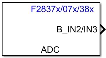
ADC Block #
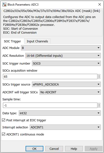
An individual ADC block controls the analog to digital conversion of a single analog channel. This block provides the parameters to select the relevant module, resolution and trigger signal for the required analog channel. ADC interrupt can also be enabled for a channel, if required.
In this example 16-bit ADC reads the measurement for DC Link Voltage and Phase Current. Both conversions are triggered from ePWM1 block while the End of Conversion for DC Link Voltage measurement generates the interrupt signal.
For more information, see chapter 11 of this document: https://www.ti.com/lit/ug/spruhm8h/spruhm8h.pdf.
Hardware Interrupt #
F28379D Microcontroller has a hardware interrupt for triggering action on different events. Selection of interrupt is based on the PIE Vector Table. Details relating PIE Vector Table can be viewed in the below link:
https://www.mathworks.com/help/supportpkg/texasinstrumentsc2000/ref/c28xhardwareinterrupt.html
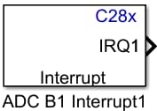
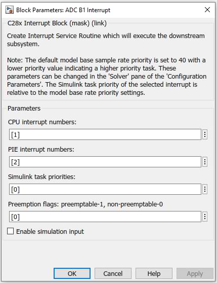
In this example, the interrupt block triggers the control algorithm; hence computing the duty cycles for next PWM cycle. This example uses the conversion completion interrupt on DC-Link Voltage measurement.
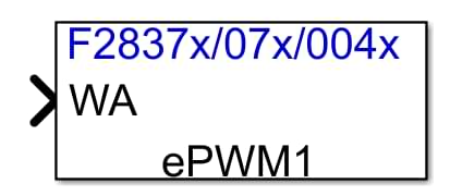
ePWM Block #
The ePWM block controls the PWM signal. Each block contains two PWM signals: ePWMA and ePWMB. Event Trigger section can be used for the ePWM Hardware Interrupt and synchronization with other modules. The Deadband Unit controls the deadtime between the PWM pair.
In this example, the ePWM block generates the PWM signals and sends Start of Conversion (SOC) signal to the ADC Modules.

For more information, see chapter 15 of this document: https://www.ti.com/lit/ug/spruhm8h/spruhm8h.pdf
Specifications #
Following table provides relevant implementation specifications:
| PARAMETER | VALUE |
| PWM Frequency | 10 KHz |
| Output Required Frequency | 15 Hz – 25 Hz |
| DC Link Voltage | 300V – 600V |
| Three-Phase Motor Rating | 380VL-L /50Hz |
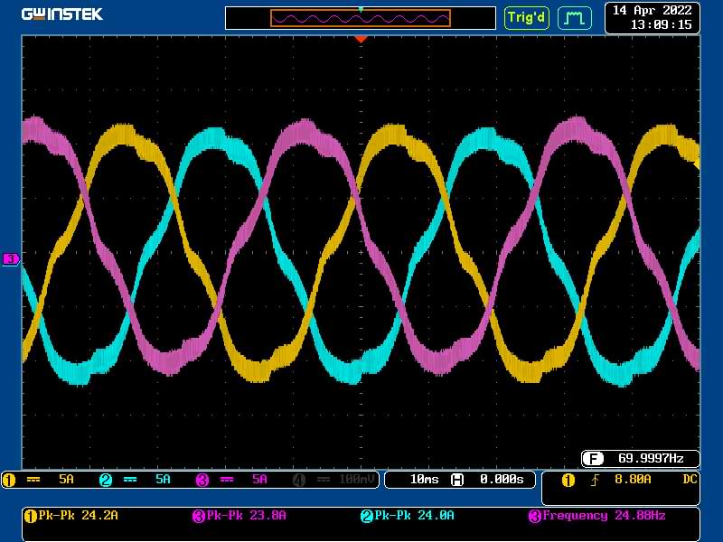
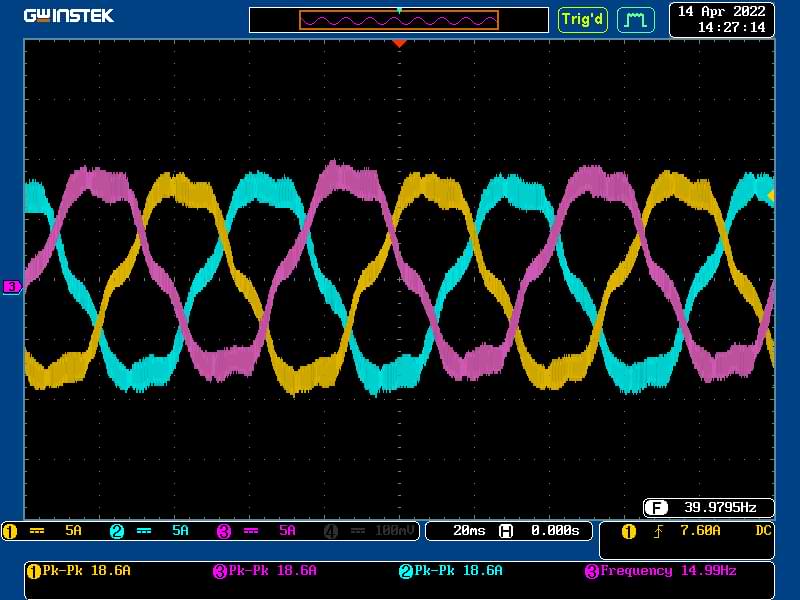
Results #
This section provides the output current waveforms for three phases at different required frequency which can be set in the model described above. Relevant measurements are also available in the images.
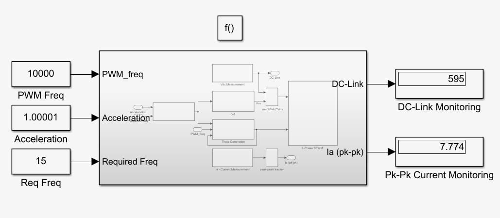
Monitor and Tune #
When a host machine gets connected with the target board, the results can be monitored and debugged by using display in the MATLAB/Simulink. For Tune and Monitor, click on the green icon in the hardware tab.
- Analog measurement of DC Link Voltage and Peak-Peak leg current (Ia) is monitored in the Simulink using the Display block.
- Required Frequency, PWM Frequency and Acceleration can be varied in real-time using constant blocks.